 |
|
THE CAN!
(c) by Carl Chetta 1997
Text, pictures and sounds by Larry Lund
Background graphic and logo by Doug Ferguson
 |
Introduction
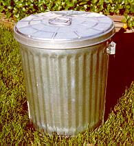
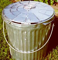
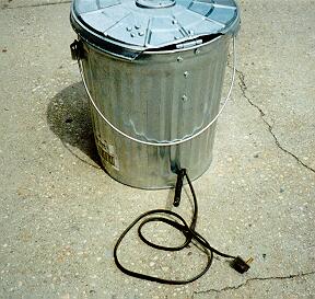
A normal looking ten gallon metal trash can suddenly comes alive! When a switch is tripped, a sequence of three things occur, all in the blink of an eye. First, the lid flips open, hinged in the back, sent up and held by a screen door closer working in reverse, acting as an air-driven actuator. Immediately following this, a grotesque head is sent flying up and out towards you, about 10" or so, as quickly as a little rocket. Finally, the entire 10 gallon can springs up in the air, rising about another 6-10 inches off the ground. What started out as a two foot tall garbage can winds up being nearly four feet tall. All this action is accompanied by a frightening air horn blast!
This all happens in a split second, so the effect is startling, to say the least. The most disorienting thing is that this little trash can - an everyday, inanimate object - moves so quickly, giving you the distinct feeling that it is on its way to a close, personal encounter with your head... and then, there is the air horn, meant to startle even the bravest of souls!
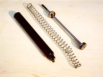
This project uses four pneumatic screen door closers, functioning in reverse as air rams. One of these must be altered, in order that the four do not all operate at the same moment the air pressure is applied. If they did so, the head would hit the lid on the way up, and then try to retract after the lid closed, causing the mechanism to hang, and probably damage itself.
Carl found out that the screen door ram cylinder's crimped end can be straightened out enough to get the cup out that holds all the guts of the closure inside the cylinder. Once you do this, the spring can actually be removed from the piston. This allows the first ram for the lid to activate without much of any resistance, quickly clearing the road for the next motion - the head flying up and out at you! (A weaker spring, external to the actuator, is used to pull the lid back down after the cycle is completely over.)
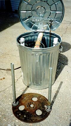
To complete the process, the whole can stands up on rams which are projected through the bottom of the can, and pushed against a relatively heavy flywheel - a piece readily found at any automotive scrapyard.
Construction
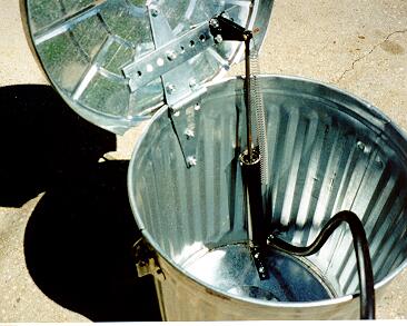
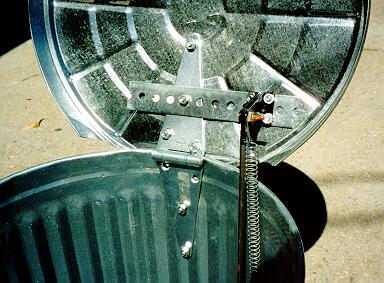
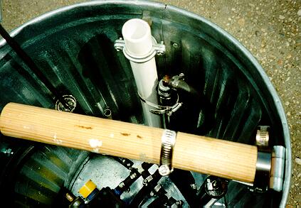
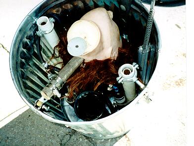
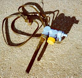
This is basically what the assembled parts look like without the head and mask. Test each stage of the construction as you proceed. It will make the job much easier if you can detect any problems as you go along.
2. The garbage can:
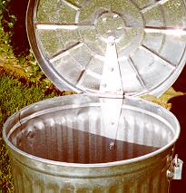
Attach a 6 inch strap hinge to the inside of the garbage can and the lid. Some trimming of the lid where the hinge attaches will be necessary to allow the lid to raise and lower properly. You should be able to raise the lid to an almost fully upright position.
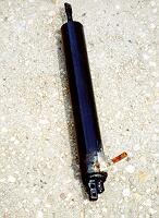
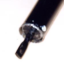
3. Preparing the screen door closers
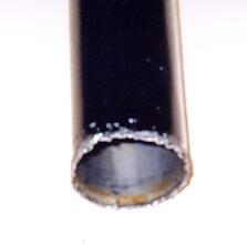
The closers that raise the lid and the head both have to be modified, since you will not be able to put a fitting in the base of the closer. Because of the way the closer is mounted, I had to devise another method. I drilled a hole near the base of the closure and silver soldered a small piece of copper tubing to accept the air hose. Before applying any heat to the cylinder, fully extend the ram and keep it extended until cool to prevent burning the internal gasket. Temporarily mount each closer, and mark the location where you want to place the fitting before drilling and soldering. The rams that raise the can off the ground must have an air inlet connector put in place of the adjusting screw. Remove this screw from the bottom of the screen door cylinder, and then screw in some kind of air connector, and attach a piece of air hose to it. I used 1/4" brass L's or T's.
4. Preparing the lid opening cylinder
This step is necessary to allow the lid to open first. You will be attaching a weak spring externally to allow the lid to close automatically .
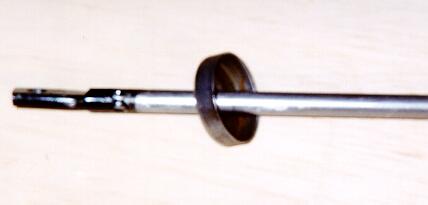
First remove the bleeder screw from the base of the screen door cylinder. This will take any compressed pressure off the cylinder. Next, you must remove the return spring from the inside of the cylinder. This will be fairly easy to do. At the top of the cylinder you will see the ram coming through what looks like a washer. This is really an inverted cup which is there to retain the spring and guts of the mechanism. Use a pair of needle nose pliers, diagonal cutters or regular pliers (I found that the diagonal cutters worked best for me. ) By slightly depressing one side of the cup you will be able to get at the crimped end of the cylinder. Carefully work your way around the cylinder, open the crimped end, and you will be able to remove the cup, and then remove the spring. While doing this step, remember that this system is under pressure from the spring - don't let the piston and rod fly out and damage something - or someone!
On some closers, there may be a small spring inside the larger spring. (Carl discovered that setup in the version he used, and he advises that you leave the small spring in, if you encounter one.) Put the cup back in and pull the ram out to approximately the location of the cup before you opened the cylinder. Drill 2 small holes through the cylinder and cup, and secure the cup in its original position with 2 sheet metal screws. This entire operation only takes about 15 minutes. You will notice now that the ram can easily be moved in and out. Replace the bleeder screw but do not tighten it all the way. This step is necessary to allow the lid to open first. You will be attaching a weak spring externally to allow the lid to automatically close. This cylinder must operate with hardly any restriction.
5. Mounting the lid opening cylinder
This cylinder will be mounted vertically along the inside back of the garbage can. You will need the screen door hardware and the external return spring. This hardware will function in the reverse of the way it works on a screen door. Mount the hardware commonly attached to the screen door to the base of the garbage can by drilling and bolting it about 5 inches to the right (or left) of a vertical line from the hinge. The attachment point should be toward the rear of the can. Attach the base of the cylinder to the mounting point. The cylinder should be able to assume a vertical position without touching the sides of the garbage can.
Attach the other piece of hardware to the cylinder ram and lift the lid to an almost completely open position. With the ram at its fully extended position, place the mounting hardware on the inside of the upright lid and mark the position of the mounting holes on the lid. You might want to put some flat steel on the inside of the can for extra support, as the ram forces the lid open violently, and might unduly stress the thin metal of the garbage can.
Drill and mount the rest of the parts. Test the operation by manually opening and closing the lid. If it is set up correctly, the lid will open to a nearly fully open position , when the ram is at its maximum extension.
Attach a spring to the base of the cylinder and the top of the ram. The spring does not have to be very strong, just enough to pull the lid closed. Gravity will do most of the work.
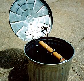
6. Mounting the head lifting cylinder
A head is attached to a small segment of a broom stick. Imagine this piece as the screen door. The closer is mounted vertically on the front of the inside of the can. I used the 5 inch hinge, and Carl used screen door closer parts. The 5 inch hinge makes for a cleaner assembly, and is attached to the inside top of the front of the can. The working end is attached to the broom stick (like a door). The head is horizontal upside down just under the lid with the face looking up and toward the back of the can. After the lid is opened, the head is projected up and forward at you. This all happens very fast.
7. Prepare the internal sleeve's for the lifting cylinders
Cut 2 pieces of 1 inch PVC to a length of 18 inches each. Put the 1 inch split rings around the pipe and mount it to the inside of the garbage can, by drilling a hole in the side of the can near the top and bolting the split ring to the side of the can. Position this evenly on both sides of the can. Cut a hole in the bottom of the garbage can for the base of the PVC pipe. The hole should be cut so that the 1/2 pipe attached to the flywheel can enter it without any restriction.
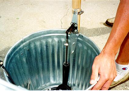
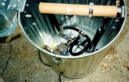
8. Mounting the lifting cylinder
The lifting cylinder is attached to the PVC pipe with a Stainless Steel clamp. The ram is facing the bottom of the can. The bottom of the PVC should go just into the base of the can. At that point, mark the location of the ram on the bottom of the can and drill a hole for it to extend through the base of the can when the compressed air is applied. The rams just push on the flywheel raising the can the length of the ram. The flywheel, being very heavy, stabilizes the whole assembly.
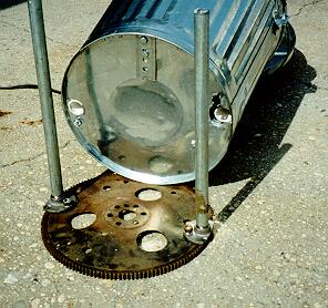
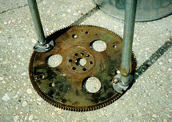
9. Flywheel assembly
The flywheels I have encountered have some 1/2" holes near the outer edges. Attach the 1/2" threaded flanges loosely with nuts and bolts to each side of the flywheel. Attach the 1/2" threaded pipe to each flange. Slide the flywheel assembly into the base of the can, through the PVC sleeves. Adjust the flywheel so it fits evenly into the base of the garbage can, then tighten the nuts and bolts that hold the flange to the flywheel. The flywheel assembly is not physically connected to the garbage can, it simply forms a weighted base with 2 vertical pieces of pipe attached, that the garbage can will be raised on. You should be able to slide the flywheel assembly in and out easily. Once this is all done, hacksaw the flanges so they are even with the edge of the flywheel.
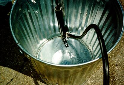
10. Assemble the air lines
The washing machine solenoid should be placed inside the can, and you must cut a hole through the rear of the can for the air line and the electric cord. Attach the air line hose using the plastic T's and clamps to all four screen door closers - and the air horn, if one is to be used.
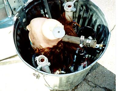
11. Attach the head and mask
The head should be attached to the broom stick handle and the face looking up and toward the back of the can. Adjust the head and mask so that they do not touch anything as they are activated.
Controlling it
I like to have complete control of my effects
so I opted for the following method of controlling the device.
I have a lot of effects that I have to turn on and off, and so I
decided to do them all remotely. I picked up a Stanley remote control
system from home depot. It consists of a wireless hand held remote
with 8 on/off buttons and a base unit that plugs into any wall
outlet ($39.95). The base unit has an antenna that receives
signals from the remote and transmits them through your house
wiring to any lamp or appliance module you have plugged in (Lamp
module $9.95 appliance module $12.95). The modules are
addressable. Anything plugged into the modules can be controlled
by the remote.
Here 's the catch...
My house has two 110 volt lines coming into the circuit breaker box. If a module is not on the same phase (110 side) as the base unit it doesn't work! I made a call to Stanley, and they told me I had to purchase a Leviton signal bridge to bridge the 110 volt lines. They don't sell them. I found one at my local electrical supply house ($42.50). I took it home and read the directions and found out I must install 2 15 amp dedicated circuit breakers (each $7.50) in my box to install the signal bridge. I wired it in myself and it really works fine. The problem I have is that Stanley had nothing in their directions to indicate that you might have this problem. As you can see, this really increases the expense.
Some tips
You can now dress up the head with a mask of your choice.
You can also use a bicycle air horn (rubber bulb removed) attached to the air supply, which works well to create some sound if you can't get an air horn trumpet.
Material list:
| Brinkmann ST-103 10gal. Heavy galvanized steel garbage can with lid. | Found ours at Pergament stores
in NY |
$9.99 |
| 6 inch strap hinge | Hardware store | $ 3.79 |
| 5 inch strap hinge | Hardware store | $ 2.00 |
| 2 10 inch Screen door hydraulic cylinders | Home Depot | $ 6.99 |
| Hose clamps | Your pick | $ 5.00 |
| Spring from dryer | Your pick | $ 1.00 |
| 2 each of 1/2 inch threaded flanges | Home Depot | ea. $ 1.77 |
| 2 each of 1 inch split rings. (Galvanized hanger) | Home Depot | ea.$ 1.53 |
| 1/2 inch black pipe threaded on both ends, 30 inches long. This will be cut in half. I used galvanized pipe as they were out of black pipe. | Home Depot | $ 4.00 |
| 2 pieces of 1 inch PVC about 18 inches each. | Home Depot | $ 3.00 |
| 12 inch foreign car automatic transmission flywheel, this does not have to be a good flywheel, but must be 12 inches. | Transmission repair facility. | $10.00 maybe less |
| 2 12 inch (or longer) Screen door hydraulic cylinders | Home Depot | $ 6.99 |
| Ugly mask/head | Your pick | $ 15.00 |
| Piece of broomstick for head about 10 inches long. | Scrounge | $ .00 |
| Plastic tee's, I used 3/8" for air hose | Automotive supply | ea. $ 1.49 |
| Clothes washing machine solenoid valve (hot/cold) | Washing Machine repair place. | $ 2.00 |
| Cap for one side of valve. | Garden supply | $ 1.00 |
| 120VAC line cord to connect to the washing machine valve. | Scrounge it | $ .00 |
| Air hose for all the air lines. Cut and clamp all fittings | Scrounge it | $ .00 |
| Air horn Trumpet | Scrounge | $ 8.00 |
| Miscellaneous nuts and bolts | Hardware Store | $ 5.00 |
The device will operate with 25-35 lbs of air pressure, and perhaps less.
Check out The-Can's big brother "Trash Can Trauma"
Click here to go back to my Halloween page.
Click here to go back to Larry Lund's Home Page
Click here to go to my Sons of Norway Page
Click here to go to my fishing Page
![]()
Web page design (c)
by:
Lund Consulting Service
Phone: (516) 231-8790
e-mail: consult@llund.com
Last Modified on: January 2021